Input-Output
From eedomus - Documentation
Contents |
Warning
The use of the wired Input-Output is an operation that requires a good knowledge of electronics and should be reserved for 'advanced users'.
The use of improper voltage, creating short circuits', can permanently damage your eedomus.
This feature is new and experimental. It may not work on every box. Connectors 'A3, A4, B3, B4, C3, C4' may be ineffective on certain box.
Introduction
The wired connectors can be used for the following features.
-
 Pulse counting with pin


-
 Digital input (Contact sensor) with pin


 and (3 buttons above the eedomus.
-
 Actuator 0-3-5V with pin


 +
+ +
+ +
+
 +
+ +
+ +
+
-
 Voltage sensor (Analog sensor) from 0V to 6.6V on pin


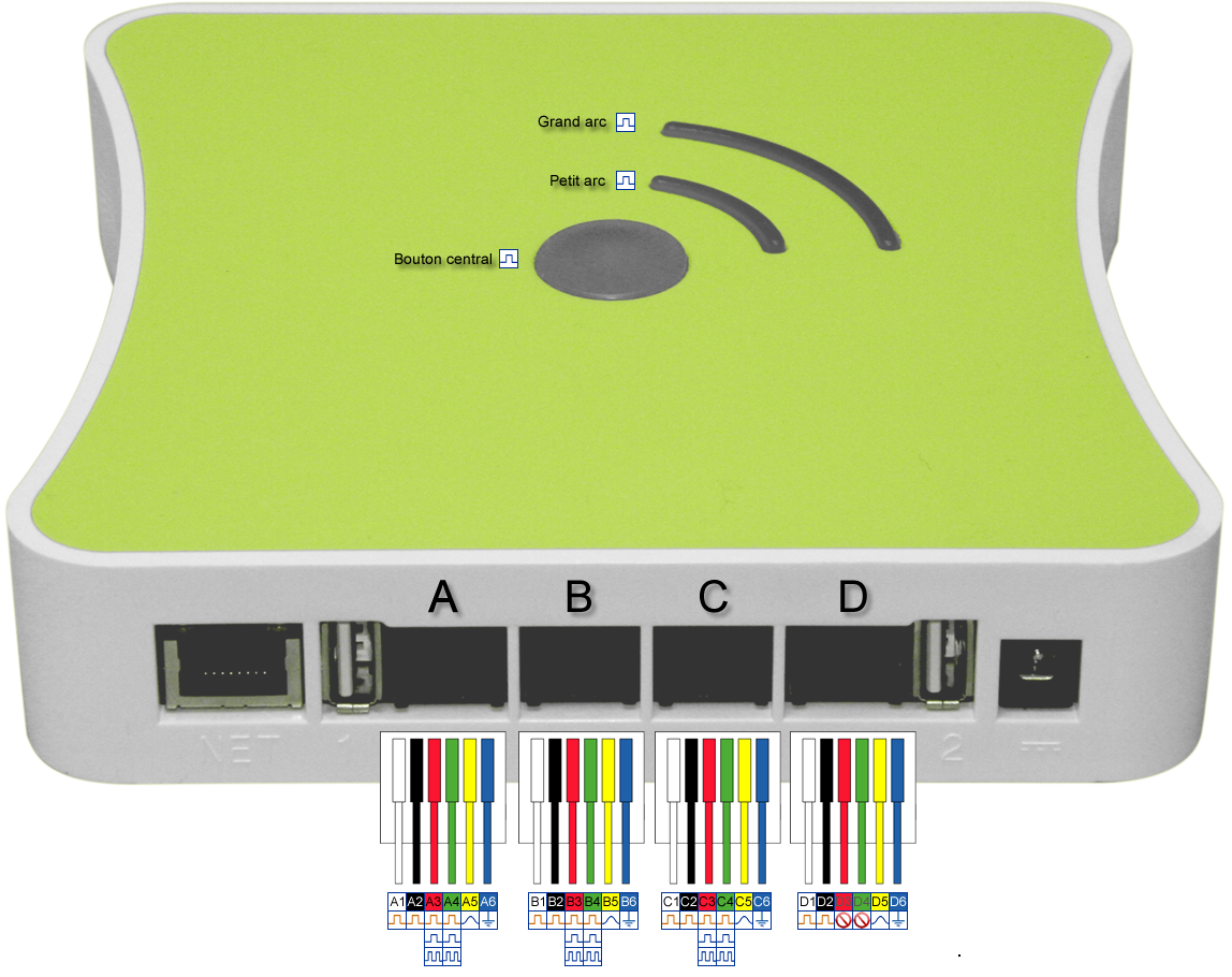
Connection Diagram
The pins are located on the 4 RJ12 connectors of your eedomus. They are labelled A, B, C and D.
Pin functions
![]() +
+![]() +
+![]() +
+![]() : may be actuated togetherbetween 0V and +5V
: may be actuated togetherbetween 0V and +5V ![]()
![]() +
+![]() +
+![]() +
+![]() : may be actuated togetherbetween 0V and +3.3V
: may be actuated togetherbetween 0V and +3.3V ![]()
![]()
![]()
![]()
![]()
![]()
![]() : may be actuated one by onebetween 0V and +3.3V
: may be actuated one by onebetween 0V and +3.3V ![]() or use as contact sensor
or use as contact sensor ![]() or Pulse counter
or Pulse counter ![]()
![]()
![]()
![]()
![]() : are analog input, that can mesure a voltage between de 0V à +6V
: are analog input, that can mesure a voltage between de 0V à +6V ![]()
![]()
![]()
![]()
![]() : are ground
: are ground ![]() (All linked together).
(All linked together).
![]()
![]() : cannot be used File:Iono.png
: cannot be used File:Iono.png
To be completed
Documentation in process.


